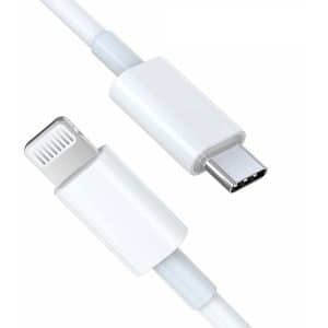
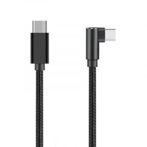
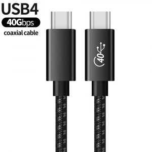
USB-C, or USB Type-C connector, is a 24-pin connector (not a protocol) that supersedes previous USB connectors and can carry audio, video and other data, e.g., to drive multiple displays, to store a backup to an external drive. It is a versatile and widely adopted connector standard that has become increasingly common in modern devices.
USB-C Pinout Definition:
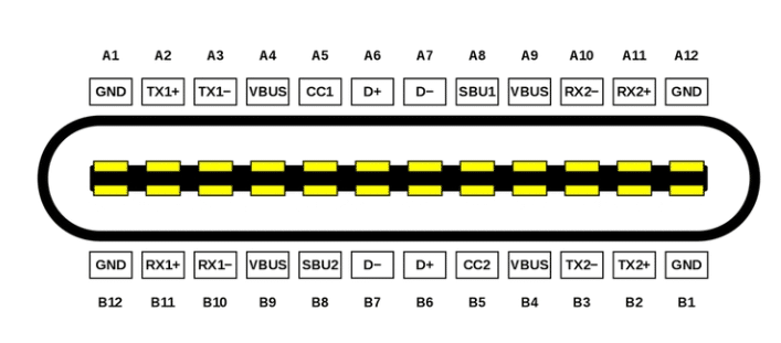
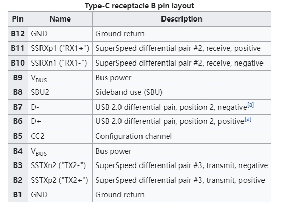
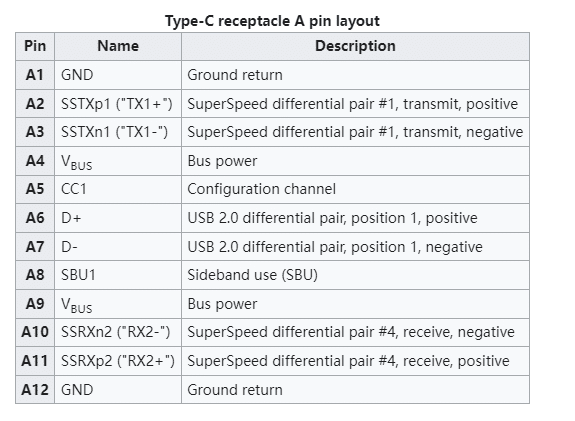
USB C pinout diagram attempts to be reversible and has 24 pins. The USB-C connector has a pinout that defines the purpose and function of each pin within the connector. The USB Type C pinout specification outlines the pin configuration, and it includes multiple pins for various functions such as power delivery, data transfer, and alternate modes. Here is a brief overview of the USB-C pinout
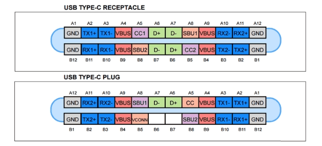
Type-C Receptacle
While the USB-C receptacle features 24 pins, not all need to be utilized. Simple devices like microcontrollers and low-power sensors can tap into GND and VBUS for power. By setting up resistors on the CC lines and detecting capabilities at the host, power delivery of 1500mA and 3000mA can be requested.
USB C Plug
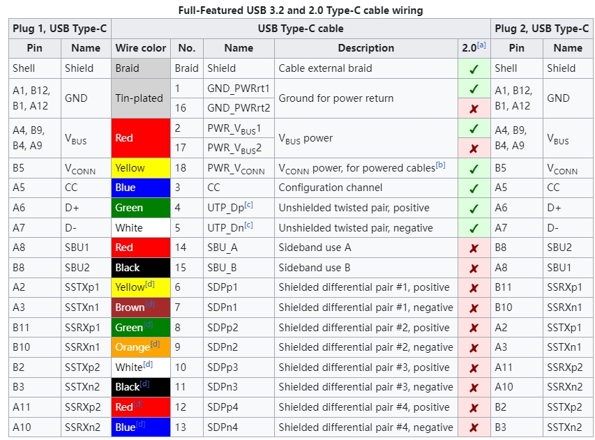
The USB-C plug is the connector that mates with the USB-C receptacle, creating a standardized interface for a wide range of electronic devices. The USB Type-C plug has a symmetrical design, allowing for reversible connections, and it features a specific pinout to define the function of each pin. Here’s an introduction to the USB-C plug pinout:
Vbus (Voltage Bus): Pins A1 and B1 deliver power, accommodating charging and device powering with a potential voltage of up to 20V through Power Delivery (PD) negotiation. The VBUS and GND pins are power and the return paths for the signals. The default VBUS voltage is 5 V but the standard allows the devices to negotiate and choose a VBUS voltage other than the default value. The Power Delivery allows VBUS to have a voltage up to 48 V. The maximum current could be also raised up to 5 A. Hence, the USB Type-C could deliver a maximum power of 240 W.
D+ and D- (Data Lines): Pins A6 and A7, and B6 and B7, ensure high-speed data transfer, supporting various USB standards like USB 2.0, USB 3.0, and USB 3.1 Gen 2.
CC (Configuration Channel): Pins A5 and B5 facilitate communication between devices, negotiating power requirements, roles (source or sink), and configuration details.
SBU (Sideband Use): Pins A2 and B2 serve for sideband signals, enabling Alternate Mode signaling for non-USB functions like DisplayPort or HDMI.
ID (Identity): Pins A4 and B4 detect cable plug orientation and aid in accessory identification, determining whether a device acts as a power source or sink.
GND (Ground): Pins A3 and B3 provide the necessary ground reference for power and data lines.
It’s important to note that the pin numbering is specific to the USB Type-C plug, and the same pinout is applicable to both ends of a USB-C cable. Additionally, when connecting devices, the communication between the CC pins is crucial for proper Power Delivery negotiation and role detection (whether a device is a power source or power sink).
UFP, DFP, or DRP: Understanding Port Roles
When two devices connect via USB, one assumes the role of a host with a downstream-facing port (DFP), while the other becomes a peripheral device with an upstream-facing port (UFP). Certain products, like mobile phones, can adapt to either role depending on the connected equipment. Creating a host device, which serves as a power source for other devices, involves implementing a Downstream Facing Port (DFP), typical in hubs or PCs. Conversely, developing a device such as a microcontroller, light source, or motor, which requires power, entails incorporating an Upstream Facing Port (UFP). Devices capable of assuming both roles are known as Dual Role Ports (DRP).
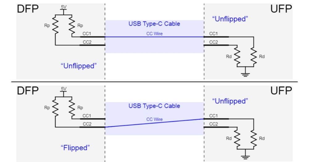
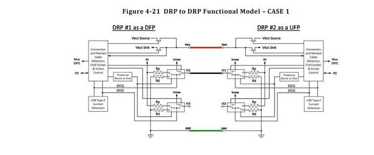
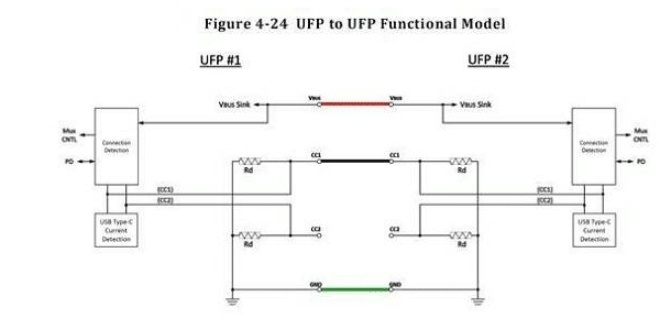
Detecting a Connection: The Simplicity of Voltage Measurement
Detecting a connection is straightforward with USB-C. By measuring the voltage on CC1 and CC2 pins, one can determine cable connection, orientation, and the type of connected device—whether it’s a host or a peripheral.
USB Power Delivery (PD): A New Era in Charging
Modern computers equipped with USB-C for charging can leverage Power Delivery (PD) to transfer up to 5A at 48V, providing a staggering 240W of power. While early PD implementations posed challenges, advancements in second-generation ICs are making PD support more accessible over time.
Alternate Modes: Beyond USB
USB-C isn’t confined to USB protocols alone. With alternate modes, it can replace HDMI and Thunderbolt cables, negotiating capabilities over the 24-pin cable for diverse functionalities. This requires circuitry for capabilities detection and line switching.
The Future of USB-C
USB-C is the future of connectivity. Its versatility, power delivery capabilities, and alternate modes make it the ideal solution for a wide range of devices. As the technology continues to evolve, we can expect even more features and functionality to be packed into this tiny connector.
Related Products
Wandkey Electronic Co., Ltd – Your Trusted Partner for Premium Phone Accessories
Wandkey Electronic Co., Ltd is a leading manufacturer specializing in high-quality phone accessories, offering a full range of USB-C Cables (2.0/3.0/3.1/3.2 Gen 2/USB4), Lightning Cable, iPhone Charger cable, PD Fast Charer, GaN Wall Chargers, Car Chargers, and more. With UL, CE, RoHS, Reach, PSE, KC, FCC, UKCA certificate, ensuring top-tier quality and safety.
What We Offer
We provide OEM & ODM services to help brands and businesses customize their products, including:
✅ Custom Branding & Logo Printing – Enhance your brand presence with personalized designs.
✅ Tailored Product Specifications – Customize cable lengths, charging power, materials, and more to fit your needs.
✅ Certified and High-Quality Manufacturing – Strict quality control and compliance with international safety standards.
✅ Packaging Customization – We offer bulk packaging, retail packaging, and eco-friendly solutions.
✅ Technical Support & After-Sales Service – Professional guidance from product development to after-sales assistance.
Who We Serve
Our business model is B2B wholesale, catering to brands and manufacturers who require premium charging accessories. Our main customers include:
✔ Phone accessory brands looking for high-end charging solutions.
✔ Electronics and smart device manufacturers needing reliable charging components.
✔ Medical equipment companies, monitoring system providers, and other industries requiring certified power solutions.
Looking for a reliable supplier for premium USB cables and chargers? Contact us today to discuss your project needs and get a customized solution tailored to your brand.
Top Topics
2025 Latest MFi Authorized Manufacturers list
Differences of Lightning Connector
How to check MFI Certification
How to get MFI Certification for Your Brand?
Why does the MFI Certified Lightning Cable so expensive?
MFI Product Packaging Requirement?
Disassemble MFI Lightning Cable
How do we guarantee the quality?
How to identify counterfeit or uncertified Lightning connector accessories
How to Choose Fast Charging Cable for Your Phone
How do I choose a USB-C cable?
Differences between USB 3.0 3.1 and 3.2
Test on USB C to USB C 3.1 Cable

