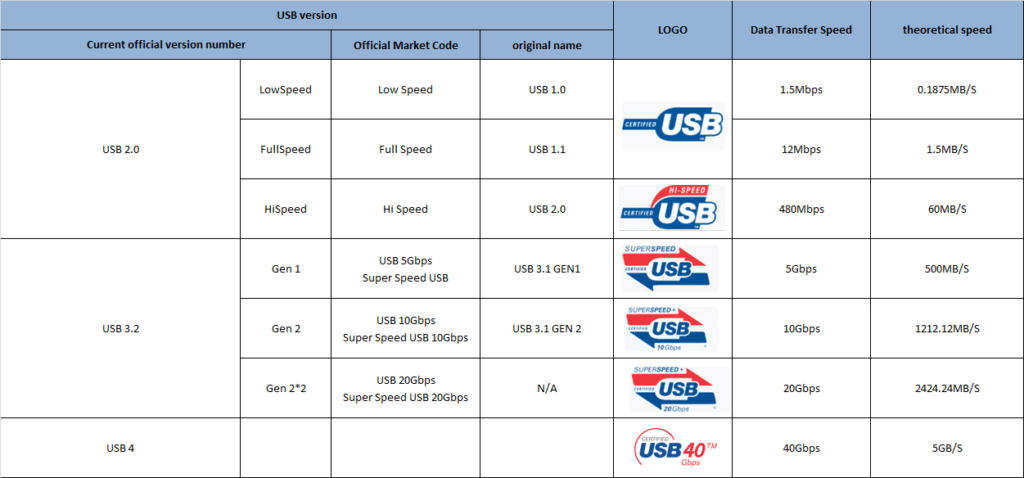
Overview of the various versions of USB
USB Type-C is an interface that is becoming popular in both computers and mobile phones. As a transmission standard, the USB interface has always been the main data transmission method when we use personal computers, from portable U disks to mobile phones with amazing capacity. The hard disk relies on this standardized transmission method, unified interface, and unified transmission protocol. It is the main way for people to exchange data and materials with each other except the Internet. It can be said that the USB interface is the foundation of today’s personal computer. One of the cornerstones of efficient life – from the original USB Type A to today’s USB Type C, the transmission standard has undergone generation after generation of changes, even if the same Type C interface, there are huge differences between each other , the historical versions of USB are summarized as follows:

The well-known USB icon (pictured below) is inspired by the weapon “Trident” of Neptune (also the name of Neptune) in Roman mythology, a powerful three-toothed harpoon. However, to avoid the harpoon-shaped design implying that people take their USB storage devices and plug them around (forks). The designer modified the three tines of the trident, changing the left and right triangles into circles and squares respectively. The three different shapes mean that a wide variety of external devices can be connected using the USB standard. Now this icon can be seen on the connectors of various USB cables and equipment sockets. Now USB-IF has no certification requirements and trademark protection for this icon, but there are requirements for different types of USB products. The following are the USB logos of different standards. For reference.
USB 1.0 -> USB 2.0 Low-Speed
USB 1.1 -> USB 2.0 Fow-Speed
USB 2.0 -> USB 2.0 How-Speed
USB 3.0 -> USB 3.1 Gen1 -> USB 3.2 Gen1
USB 3.1 -> USB 3.1 Gen2 -> USB 3.2 Gen2 x 1
USB 3.2 -> USB 3.2 Gen2 x 2
USB 4 -> USB 4 Gen3 x 2
1.Overview of hardware interface changes in each version

Among them, the latest USB4 standard currently only supports the Type-C interface, while USB4 is compatible with the characteristics of various interfaces/protocols such as Thunderbolt, USB, Display Port, and PCIe. It has laid the cornerstone of popularization and promotion for the upcoming large-scale popularization of USB4.
2.Type-A/Type-B and Mini-A/Mini-B and Micro-A/Micro-B
1) Electrical characteristics of Type-A and Type-B
The line sequence includes VBUS(5V), D-, D+, GND. Since USB uses differential signals to transmit data, there are two differential signal lines, D- and D+. Among them, the two contacts of VBUS and GND are relatively long, and the two contacts of D- and D+ are relatively short, so when the USB is plugged in, it will supply power first, and then connect the data line. When unplugging, first disconnect the data cable, and then disconnect the power cable.
2) Electrical characteristics of Mini-A/Mini-B and Micro-A/Micro-B
The Mini USB and Micro USB have 5 contacts, and the line sequence from left to right is VCC (5V), D-, D+, ID, GND. It can be seen that they have introduced a fifth line based on usb2.0: ID line
3) USB OTG interface (can be used as HOST or DEVICE)
USB is divided into HOST (host) and slave (or DEVICE). Some devices may sometimes need to be HOST, and sometimes they need to be DEVICE. Of course, it can be realized if equipped with two USB ports, but it is too wasteful of resources. If a USB It is great that the interface can be used as both HOST and DEVICE, and it is much more convenient to use; for this reason, USB OTG came into being.
So here comes the question, how does a USB OTG interface know whether it should work on HOST or DEVICE? The ID detection line is used for OTG function (the high and low levels of the ID line indicate whether the USB port is working in HOST or DEVICE mode)
ID=1: OTG device works in slave mode.
ID=0: OTG device works in host mode.
Generally, the USB controller integrated in the chip supports the OTG function, and provides a USB OTG interface (connected to the usb controller) for the insertion of Mini USB or Micro USB and other interfaces with ID lines.
If there is only one Mini USB interface (or Micro USB interface), if you want to use the OTG host mode, then you need an OTG cable. For example, the OTG cable of Mini USB is as shown in the figure below: It can be seen that one end of the Mini USB OTG cable is a USB A socket, and the other end is a Mini USB plug. Insert the Mini USB plug into the Mini USB OTG interface of the machine, and the USB device to be connected Plug it into the USB A socket on the other end, such as a U disk or something. The USB OTG line will pull down the ID line, so that the machine knows that it is going to be a host to connect to an external slave device (U disk).
Related Products
Related Topics
2022 Latest MFi Authorized Manufacturers list
Differences of Lightning Connector
How to check MFI Certification
How to get MFI Certification for Your Brand?
Why does the MFI Certified Lightning Cable so expensive?
MFI Product Packaging Requirement?
Disassemble MFI Lightning Cable
iPhone 14 Pro may use USB C Charging Port
How do we guarantee the quality?
How to identify counterfeit or uncertified Lightning connector accessories
How to Choose Fast Charging Cable for Your Phone
How do I choose a USB-C cable?
Differences between USB 3.0 3.1 and 3.2
Test on USB C to USB C 3.1 Cable


